Keeping digital strip connected
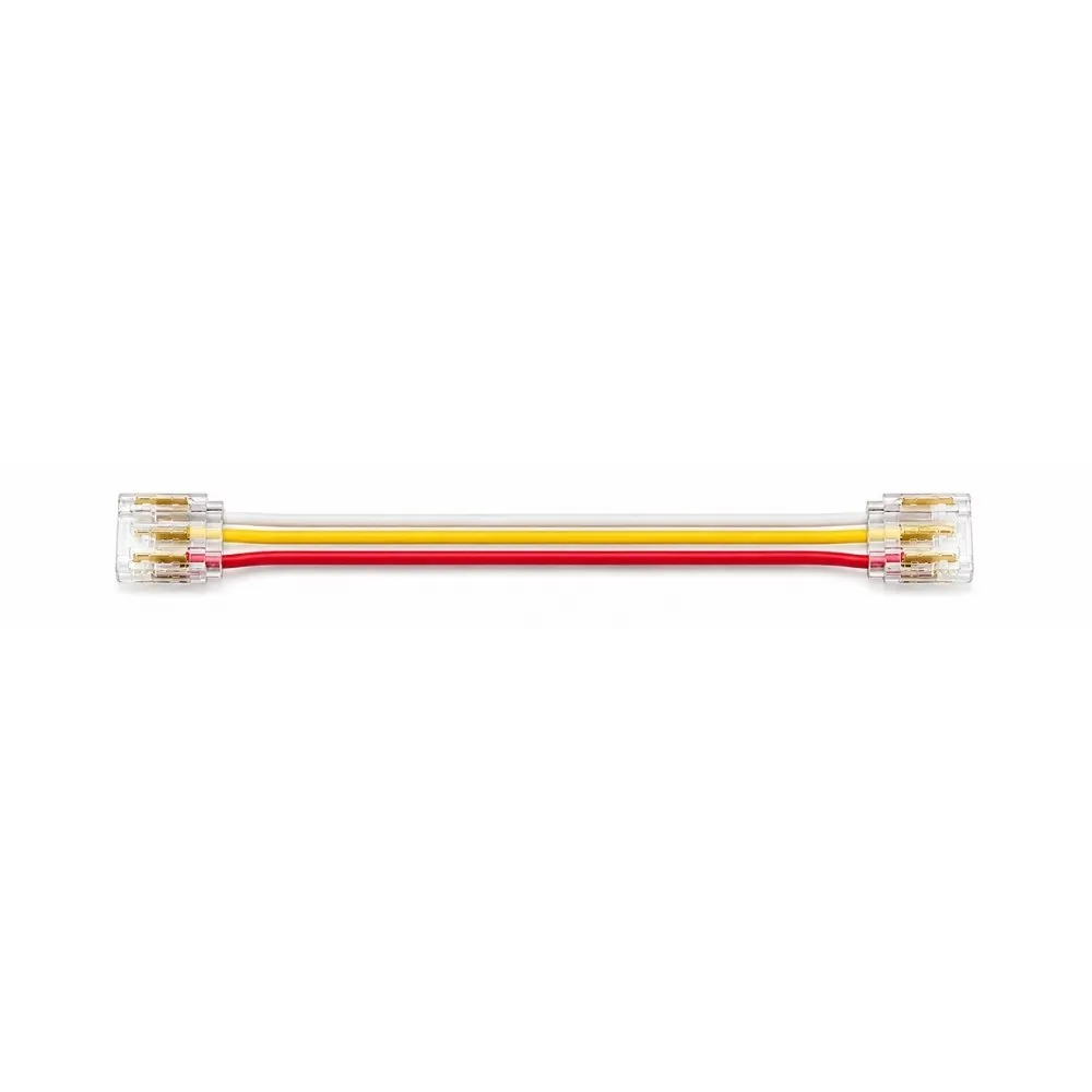
With SPI LED strip, each section passes data along to the next, so the joints in a run are more than just a power connection. The CANOLIGHT CL-AST-SPI-C12BBW-LV PCB to PCB connector is made to join two pieces of COB SPI strip through a length of wire, carrying the connection from one section to the other across a corner, a gap or an obstacle, while preserving the seamless, dot-free look that makes COB strip so appealing.
Sized for 12 mm PCB strip
The connector is designed for strips with a 12 mm PCB width. Matching the width is essential: the strip must slide squarely into the head so each pad lands on its contact. Before installing, confirm that your strip is an SPI COB strip with a 12 mm PCB and compare the conductor layout with the spec sheet available in the Documentation tab. A correctly matched connector seats firmly and gives a dependable contact on every conductor.
Installation guidelines
Switch off power at the supply and the controller. Cut the strip only at its marked cut points, open each connector head, insert the strip with the pads facing the contacts and close the head until it locks. Pay close attention to the direction of the data flow printed on SPI strip, typically shown by arrows: the signal must travel from the controller side toward the end of the run, so orient each section accordingly. Keep the conductor order consistent, test the effect before fixing the strip permanently and install the driver, controller and line-voltage wiring according to local electrical code.
Applications
This SPI strip connector is ideal for animated cove lighting, chasing effects along bar fronts and back shelves, dynamic displays in retail and trade-show fixtures, gaming rooms and home theatres, stair lighting that follows your steps, and architectural accents in lobbies and restaurants. Installers use it to take digital strip around the corners of ceilings, cabinets and counters without soldering on site, which saves time and reduces the risk of damaged pads.
Tips for a reliable run
Plan your layout before cutting, marking each corner and gap that needs a connector. Keep the wire protected from sharp edges and pinch points, avoid tension on the joints and leave them accessible when possible. For the complete connector details, consult the spec sheet in the Documentation tab.